


Implementation
:
We made a FM transmitter and receiver. The tranmitter was attached to the output of the 555 timers. All the circuits and details are given below.
1) At its very basic level the FM transmitter is a
simple LC oscillator.
2) The capacitor in our transmitter is a variable capacitor
and operates on the same principle as the variable oscillator in the carrier
oscillator that we built earlier.
3) Instead of having to manually adjust this variable
capacitor it changes capacitance based on sound waves.
4) The larger the amplitude of the sound waves the
more the capacitor changes and the more that the oscillator frequency is varied.
So changes in amplitude (sound level or volume) affect the frequency of the
oscillator.
5) If the sound waves reaching this variable capacitor are very fast the the frequency of the oscillator will change very fast because the capacitor its changing very fast. So changes in the frequency of the sound waves affect how quickly the oscillator will vary.
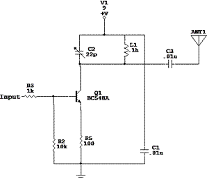
Basic FM Transmitter.
The modulating inputs chosen are 500Hz and 5kHz. One of the frequencies will control the forward channel and the other will control the reverse channel. At the receiver, we use two filters. One high pass and the other, low pass. We also use an op-amp amplifier to increase the output voltage to a suitable level for controlling the relays.
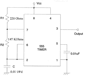
500 Hz Generator.
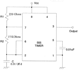
5 KHz Generator.
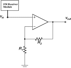
Non Inverting Amplifier.
The input-output formula for the noninverting amplifier is V(out) = ( 1 + R2/R1) V(in)
We choose R1 and R2 such that we get a gain of about 11 which will be sufficient to drive the relays on the car. The amplifier is connected to the output of the FM Receiver Module. The output of the amplifier is connected to two RC filters.
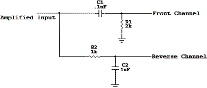
Output Filter Stage.
<<Previous(Parallel Port) Next(Obstacle Detection)>>
Copyright © 2003 Gammaworkz. All rights reserved.
CVGS
Communication System