Obstacle Detection
Home
CVGS
Obstacle Detection

Obstacle Detection
Home
CVGS
Obstacle Detection

In this project we use infrared vision system. The
car will project 2 modulated IR beams ahead and detect any reflection of these
beams on any obstacle ahead of the car. The circuit will then display a warning
in the form of a red light glowing on top of the car.
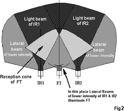
IR emitters LEDs irradiate a cone of infra red light therefore some experimenting
is necessary to determine position and best shrouding in order to prevent
that the FT receptor located in the middle receives direct IR emissions.

Inefficient Reception Cone
In the above figure is shown the main beams of the IR emitters and the lateral beams. The FT phototransistor has a reception cone depicted. Note that direct lateral emissions of infra red light reach the FT. We don't want this direct type of illumination, what we want are the reflections of the main IR beams produced.

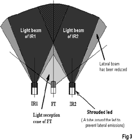
The above figure depicts how we may prevent lateral emission beams from reaching the FT. If we put some kind of sleeve or shroud around the emitter LEDs we may control how much this lateral beam will expand, i.e.: the angle of aperture.
All we have discussed relates to the horizontal plane, but similar considerations can be made considering the vertical plane. Precautions against ground reflection should be considered, i.e.: the angle from horizontal plane the IRs aim for.
Implementation
When the car is in front of an obstacle the Infrared
waves are reflected back off the obstacle. The receiver which is placed on
the car in between the two transmitting IR LED's will receive the reflected
IR waves and powers a LED which is mounted on the car. The output of the receiver
has a low current and is hence fed to a transistor amplifier connected in
between the LED and the receiver module.
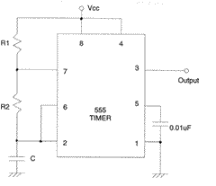
The emitter LED is powered by a 555 timer which is
set in the astable operating mode. Since the receiver has a bandpass filter
of a frequency 38kHz, we set the output of the 555 to 38kHz square wave. The
Infrared LED flashes on and off at 38kHz, thereby transmitting a 38kHz wave.
The receiver will filter out any continuous signal, so we use a duty cycle
of 33%.
The receiver has three pins. Two of which are Vcc and
Gnd. The third pin is the output pin which is active low. When there is no
signal, the output is high. When it receives a valid signal, the output goes
low. We overcome this problem by connecting the LED to the output pin and
to the Vcc pin. This way when no signal is received, the LED gets Vcc on both
the pins and it will stay off. When a signal is received, the LED gets Vcc
on one pin and Gnd on the other pin and hence it switches on and the user
is warned of the obstacle by the glowing LED.
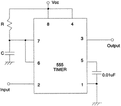
For additional utility, the output of the receiver
is connected to a 555 operating as a monostable multivibrator. Whenever a
high is obtained on the output pin of the receiver, the monostable multivibrator
turns on and remains on as long as the infrared signals are received. When
the signals are interrupted, the mono goes off after a few seconds depending
on the value of the R7-C6 combination. The one we have used is set at 1.1
seconds.
The sensitivity of the receiver depends on the current
limiting resistor R4 in series with the infrared LED. As the value of R4 is
increased, the range decreases.

R1 = 1.8 KOhms R2 = 1.0 KOhms C = 0.01uF
555 as a Astable multivibrator operating
at 38 khz.

R = 10KOhms C = 10uF
555 as a Monostable multivibrator.
<<Previous ( Communication System ) Next ( Software )>>
Copyright © 2003 Gammaworkz. All rights reserved.